MOUSE TRAP CAR TEAM 12
ENGINEERING GRAPHICS
INTRODUCING TEAM 12'S MOUSETRAP CAR
Engineering Graphics Design Class Spring 2023
Over the course of the 17 week class, we learned how to brainstorm, design, iterate, and develop 3-Dimensional models using Fusion 360. We also performed simulations to determine the capabilities of these models given loads and stresses. We used engineering drawings and methods for tolerancing and manufacturing to ensure the parts will fit as they should. These skills were then put together for the final project consisting of a working mousetrap car that was built with the help of a laser printer and 3D printer.
Stage 1:
Sketches/2D Designs
We started out with a few simple sketches and ideas of the dimensions and basic features on paper to get an idea of the shape and design of the car we were looking to make. We considered the frame length and width to obtain good center of gravity along with the optimal lever arm length to ensure the farthest distance possible. We had a few ideas for wheels and how they will be attached to the driveshaft.


Stage 2:
3D Model and simulation
-
After a good idea of the dimensions and design we were looking for, we then proceeded to generate the 3D model of it. The most important part of this stage was to create a working model to give us our first representation of how the car will look.
-
We performed a simulation consisting of a 3-point bending load of magnitude15N to provide us information on wether the frame is rigid enough.
-
The maximum acceptable deflection of the frame was to be no larger than 1 mm, and ours read 0.12mm
Stage 3:
Prototype


Wheels: Standard sized CD's
Frame (laser Cut): Our frame was a simple rectangle with some notches and puzzle-like design to make the assembly more accurate. We laser cut the frame out of Medium Density Fiberboard (MDF) which was heavier but more accessible and abundant in the lab.
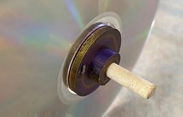
Wheel Hubs(3D Printed): The hubs were essential in keeping the wheel centered and fixed on the drive shafts. The inner piece allowed for the inner diameter of the CD to sit on while the outside washer piece slid over the hub extension and clamped the wheel tightly, small pins were also go through he hubs and wheels and prevent the CD from spinning independently of the hub.
Lever Arm: We used to zip ties along with bending the spring excess over the arm to improve the connection between the arm and the mousetrap.
The prototype car was crucial for determining problems or room for improvement. Our prototype showed us the need for weight loss, bigger wheels, and a definite way to release the drive string to allow for coasting once the lever arm has gone through its range of motion

Stage 4:
Final Design


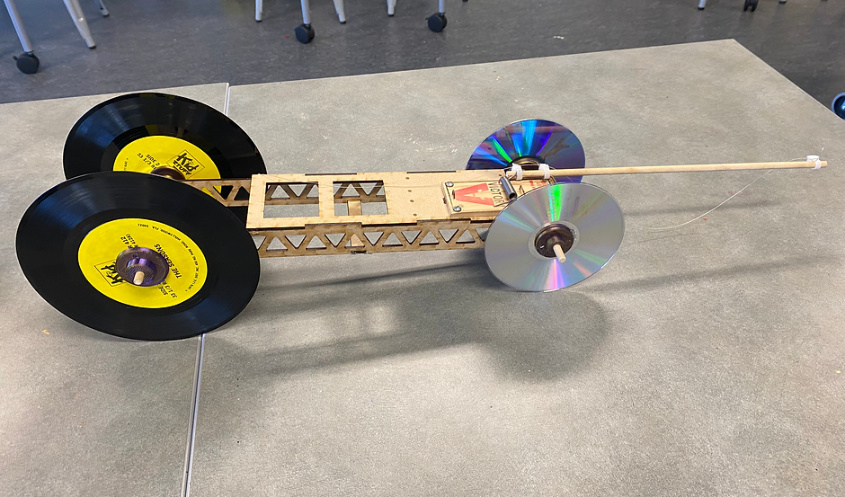
Wheels: Based on our results from the prototype, we went larger for the rear wheels and used records instead of CD's to increase the distance.
Frame (laser Cut): To shave weight from our first iteration, we went for a triangle/cheese-grater pattern as it is the best design for a weight-saving to strength ratio. We then added an additional bottom support to retain the horizontal and torsion rigidity.
Wheels hubs(3D Printed): The hubs from our prototype proved to be very effective so we continued to use them for our final car
Lever Arm: We used the same method as the prototype for attaching the Lever arm to the mousetrap.
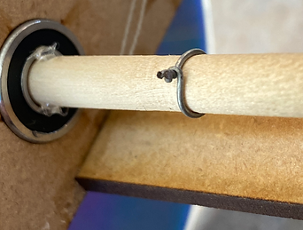
Rear driveshaft release hook: We used a small piece of aluminum wire and twisted it to tightly secure it to the shaft. Then the excess wire was cut to under an 1/8 in so the string could hook but release easily when it was supposed to.
Mousetrap: The mousetrap was attached with 4 screws that screwed into the Frames top board. the holes for the screws were a tight fit to allow for the screw to bite and tap itself into the top board.
Glue: As seen in the picture to left, we used small dots of hot glue to center the driveshafts. the glue was placed only on the inner race of the bearing so the driveshaft could move rotationally but not horizontally
Engineering Drawings
Below is a set of working Engineering Drawings to completely dimension and tolerance our entire Mousetrap car using GD&T.
Click below to see
Our learnings

Throughout the process of the mousetrap car project, we learned numerous things about how to design and build something. We learned that tolerances for parts are extremely important as we had to re drill and make the parts fit because they didn't come perfect and had some burs and imperfections from the 3D printer.
We also learned the great importance of test and tune. This stage was so crucial to our success because we were able to adjust and make changes based on the results we picked up. Without testing, we wouldn't be able to fine tune and maximize our potential.
Another major learning was our manufacturing stage. taking the time to ensure everything was put together with precise care of the glue and measuring everything to be centered. We learned this after our prototype was poorly glued with just hot glue.
Applying our learnings
After taking in account all the things we noticed we could learn from, we addressed them for our final car. We toleranced the wheel hubs and frame so that everything would seamlessly fit together to function on a higher level than before. We utilized the laser printer and 3D printer from the CSM Makerspace to cut our frames and print our wheel hubs. This allowed for us to produce a very precise car that could beat the competition (which it did!)
Winning Car!
"RAT ROD"
Our car named the RAT ROD went an outstanding 116.7 feet beating its competition by over 30 feet! With the slim and perfect shape of the CD's to the precise construction of this car, we were able to keep the car straight and drive for as long as possible. We also printed a custom vinyl decal to add some extra flare to the appearance.

